
If you’ve ever wanted to build your own electronic circuits—without soldering or ruining components—then a breadboard is the best choice. Simple, reusable, and surprisingly powerful, breadboards make learning electronics fun and hands-on. Let’s explore the breadboard basics, and why every beginner should start with one.
What Is a Breadboard?
A breadboard is a plastic board filled with tiny holes arranged in a grid. Inside, these holes are secretly connected with metal strips that allow electricity to flow. You can plug in wires, LEDs, resistors, sensors, and small chips to build circuits without soldering anything permanently.
You plug pieces together, test your idea, fix mistakes, and experiment—all safely.
A breadboard is more than just a plastic board with holes—it’s a powerful learning tool. Whether you’re a student, hobbyist, or DIY enthusiast, mastering the use of breadboard opens the door to the exciting world of electronics. Start simple and enjoy the process of making your ideas come alive.
Why Is It Called a “Breadboard”?
Before the advent of modern plastic breadboard, hobbyists used to mount components on actual wooden boards used for cutting bread. They hammered nails into the board and wrapped wires around them. Today’s plastic boards are much cleaner but the name stayed!
The Basic Layout of a Breadboard
To use a breadboard confidently, you need to understand how the holes are connected inside. Here’s the simple breakdown:
1. Power Rails (Long Side Rows)
These are long rows usually found on both sides—marked with red (+) and blue (-) lines.
- Red line → positive power supply
- Blue line → ground (negative)
Inside, each long row is electrically connected horizontally. This makes it easy to distribute power across your circuit.
2. Terminal Strips (Middle Area)
This is the main working area where you place components. Vertical Holes are electrically connected in groups of five.
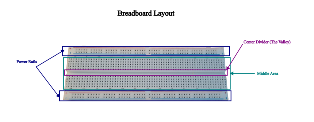
3. The Center Divider (The Valley)
At the center of the breadboard, a gap purposefully runs through the middle.
This is where you place chips like Integrated Circuit (ICs), so each side of the chip gets its own row of connected holes.
How Does a Breadboard Work?
In the middle area of the breadboard the each vertical column of holes is electrically connected. The holes act as tiny metal clips. And they are connected vertically with the same metal strip in the middle area. In power trail area each horizontal row is electrically connected. We will see how it all works when we will be making a simple project on breadboard.
This hidden network of metal connectors is what lets electricity flow through the circuit.
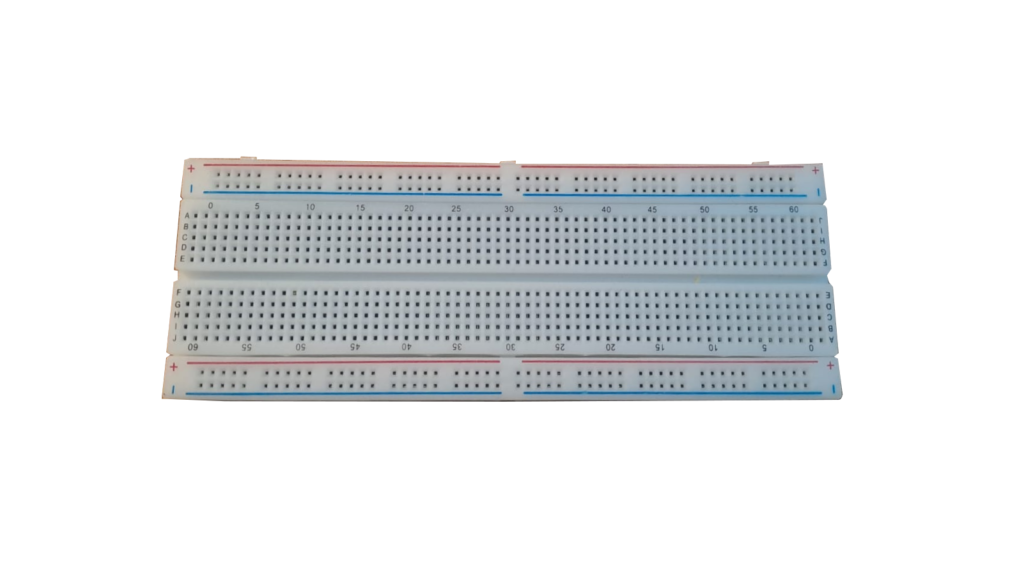
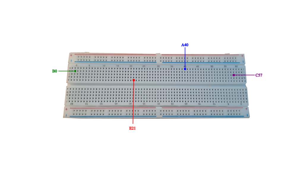
If you look at the middle area of the breadboard, you will find that rows are named alphabetically while columns are numbered from 0 to 60. This will make it convenient to locate any hole.
The way to identify any hole is to place the breadboard in front of you. Look at the Alphabets on the left for the rows and number at the top. For example if you want to place a component at hole B21. Then you need to look for B row and 21st column.
Below diagram will help you understand the holes identification in middle area of the breadboard.
What Can You Do With a Breadboard?
You can make numerous beginner-friendly project using breadboard. A breadboard opens the door to an entire world of hands-on electronics. Because it requires no soldering and everything is plug-and-play, you can build, test, modify, and rebuild circuits in minutes. Whether you’re a complete beginner or an aspiring inventor, a breadboard is the perfect sandbox for experimenting and making simple projects.
Some of the simple project ideas are as follows:
- Lighting up a simple LED
- Controlling a buzzer
- Traffic light simulation
- Controlling LED brightness
- Testing different sensors (temperature, light etc.)
A Beginner’s First Circuit: Lighting a small bulb (LED)
Lets kickstart our first simple project on breadboard. This would simply light a up a small LED bulb.
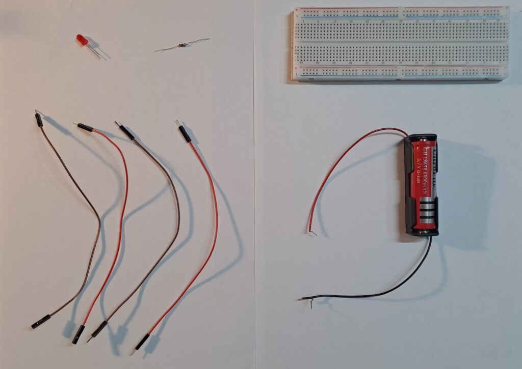
Required Components
- 1 LED
- 1 Resistor ( 82 Ohms)
- Jumper wires
- A battery (3.7 V)
- A breadboard
Note:
- The above components can be bought from any electronics shop or through online e-commerce site.
Circuit Diagram
When you start building electronics on a breadboard, you’ll often see a drawing called a circuit diagram. This diagram works like a map that shows how all the components in your circuit are connected.
A circuit diagram (also called a schematic) is a visual representation of an electrical circuit using symbols instead of real pictures.
Each component—like resistors, LEDs, batteries, switches, and sensors—is shown with standardized symbols that make it easy to understand how electricity flows.
Below is the circuit diagram for our LED light bulb project.
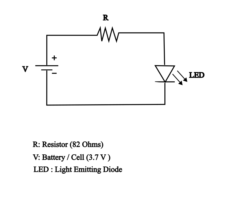
In circuit diagram shown above, note the symbol of each component. To refer to the complete list of electronics symbol, click here: Electronic Symbol
Don’t panic if you see an exhaustive list of symbols. You can get yourself familiarize the electronics symbol as you practice different projects on breadboard.
Step-by-step Instructions
Now we have our circuit diagram, lets try to implement it on breadboard using following steps:
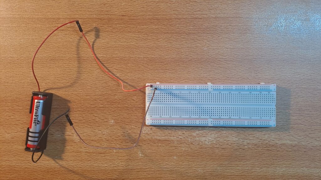
- Place the positive end of the 3.7 V battery onto the power rail characterized by red horizontal line and ‘+’ sign.
- Place the negative end of the 3.7 V battery onto the power rail characterized by blue horizontal line and ‘-‘ sign. With this we have connected the battery component on the breadboard. The below picture shows battery connections on breadboard:
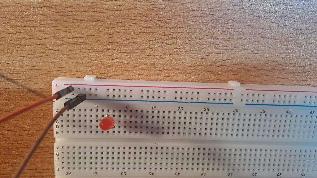
3. Insert LED anode (long leg) into the middle area. Lets insert it on the hole B15.
4. Insert LED cathode (short leg) into hole B17.
4. Insert one end of resistor into hole E11.
5. Insert the other end of resistor into hole E15( same column as LED anode).
6. Connect a jumper wire from your +3.7 V Power rail to D11 (same column as in which one end of the resistor is placed.
7. Connect the second jumper wire from GND (‘-‘ sign) power rail to D17 (same column as LED cathode.
Note: The choice of inserting LED anode and cathode into B5 and B7 are completely arbitrary. You can insert LED anode and cathode anywhere in the middle area of the breadboard as long as they are in two different columns. However once you have placed the LED anode and cathode, then make sure other components should also be adjusted accordingly so that all ends of components are connected in line with the circuit diagram.
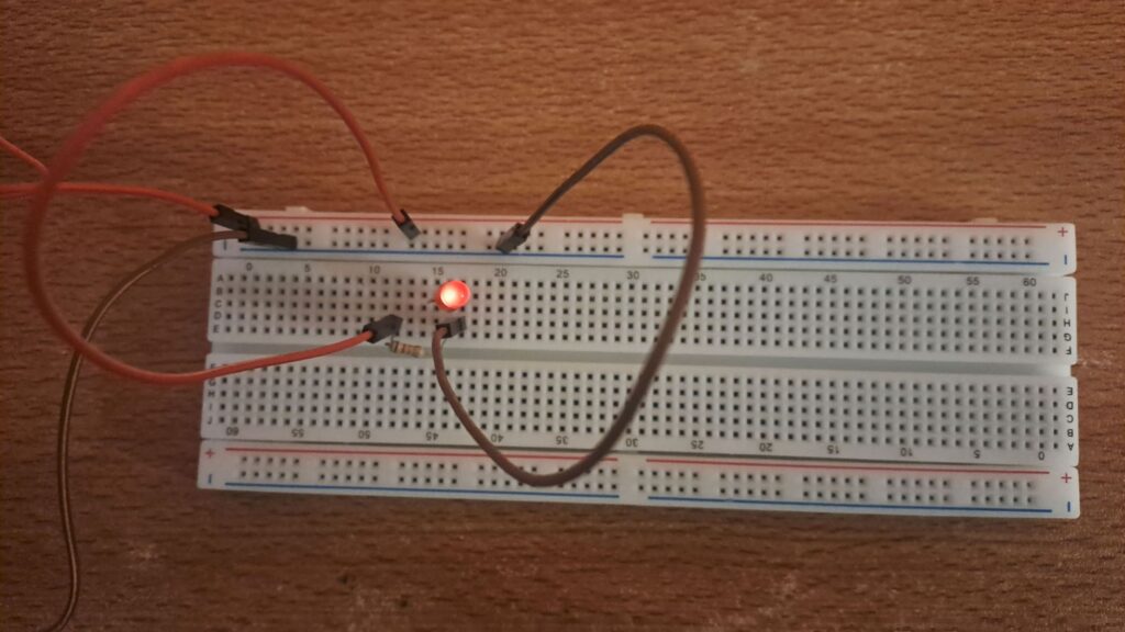
As soon as you placed the components in the arrangement shown above. You will see the LED light is lit up. Pat your back if you are successfully able to complete your first breadboard project.
As you begin exploring other breadboard projects, remember that learning electronics is not about getting everything right the first time. It’s about curiosity, experimentation, and understanding why things work the way they do. Start small, follow circuit diagrams carefully, and gradually challenge yourself with more complex designs.
So plug in, experiment, and enjoy the journey of discovery. The best way to learn electronics is to build it yourself.